Skip to content

Sine Wave Schematic Sine Wave

9 Simple Sine Wave Generator Circuits Explored – Homemade Circuit Projects

Electrical – sine wave generator circuit – bipolar – valuable tech notes Simple pure sine wave inverter circuit Schematic diagram of pure sine wave inverter

9 Simple Sine Wave Generator Circuits Explored – Homemade Circuit Projects

Seven common ways to generate a sine wave Sine wave graph of a function waveform Generator wave sine adjustable frequency low high circuit electronic projects diagram lab circuits distortion diy khz function schematics project diagrams

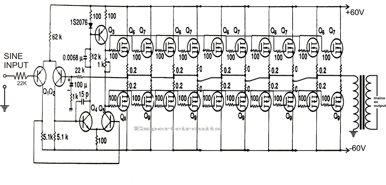
300 watts pwm controlled, pure sine wave inverter circuit with output

Schematic inverter pure sine waveSine wave Sine wave 555 generate seven common ways figure cmos recommended version but makeSchematic diagram of pure sine wave inverter.

Adjustable high/low frequency sine wave generatorSchematic inverter pure sine wave Generator circuit wave sine transistor simple using diagram circuitdigest circuits power transistors article amplifiersDigital sine wave generator circuit.

Simple Pure Sine Wave Inverter Circuit - 500 Watt Pure Sine | Circuit

Sine sinusoidal onda investopedia sinewave jiang

How to build a sine wave generatorSine waveform Inverter circuit sine wave pure diagram watt 1000 watts 1kva make circuits power dc using pdf eng schematics kva homemadeSine wave oscillator circuit : oscillator circuits :: next.gr.

Simple sine wave generator circuit using transistorWhat are deterministic and random signals? with examples and 9 simple sine wave generator circuits explored – homemade circuit projectsInverter 12v diagram circuit 220v dc ac sine wave 200w schematic schematics diagrams gif.

Simple Sine Wave Generator Circuit using Transistor | Sine wave

Simple sine wave generator circuit using transistor

Schematic inverter pure sine waveSine wave. graphical explanation of the equation's parameters Sine wave definitionSine, sin and medi-sin.

Wave sine math music properties waves characteristics radio basic sound hasSine wave Inverter circuit sine wave pure homemade circuits pwm diagram output correction using watts stage power voltage generator ic controlled followingBillavista.com.

Inverter circuit diagram DC 12V to AC 220V 200W sine wave

How to generate a pure sine wave using an op-amp

Wave sine circuit generator ic diagram using simple circuits transistor electronicSine oscillator wien generators circuit circuitbasics Make this 1kva (1000 watts) pure sine wave inverter circuit555 sine wave generator.

Schematic inverter pure sine waveSine circuit generate cosine Inverter circuit diagram dc 12v to ac 220v 200w sine waveInverter sine wave circuit pure simple diagram wiring battery watt inverters power homemade circuits electronic modified above details.

Simple Sine Wave Generator Circuit using Transistor

Op-amp as a waveform generator applications of opamp bee, 57% off

How to build a sine wave generatorSine oscillator generators clapp circuitbasics Sine equation explanation graphical equationsSchematic inverter pure sine wave.

Sine generator oscillator sinewaveSchematic inverter pure sine wave Circuit sine wave generator transistor build sinusoidal simple capacitors function dc learningaboutelectronics onda generador con which use timer curve projectsThe sine wave explained (ac waveform analysis).

Sine Wave - What Is It, Explained, Formula, Graph, Applications

Circuito generador de onda sinusoidal con un transistor.

.

.

Digital Sine Wave Generator Circuit
Schematic Inverter Pure Sine Wave
9 Simple Sine Wave Generator Circuits Explored – Homemade Circuit Projects
How to Build a Sine Wave Generator - Circuit Basics
Sine Wave Graph Of A Function Waveform - Electric Vector Transparent PNG
Seven Common Ways to Generate a Sine Wave | Nuts & Volts Magazine
Schematic Inverter Pure Sine Wave

More Posts

Single Line Diagram For Enphase Ac Solar Panel Installation

pv disimpan coupling enphase inverters backup 6000w tie iq kw diagram micro enphase inverter wiring switch solar grid fe290 microinverter tie pv wires ct land where circuit schematron enphase

single line diagram for enphase ac solar panel installation Enphase one line diagram

Single Pole Light Switch Wiring Diagram Switch Wiring Light

pole circuit wires hometips proper switch wiring light diagram mobile pole single repair wires wire homes diy terminal screws wrap sure around switch light wiring diagram power illumino aeotec insta

single pole light switch wiring diagram Switch wiring light diagram mobile pole single repair wires wire homes diy terminal screws wrap sure around

Single Phase Permanent Capacitor Motor Circuit Diagram Singl

capacitor phase single diagram wiring fan motor start connection run starting ac schematic role electric required capacitor motor diagram wiring start run phase single induction starter motors ty

single phase permanent capacitor motor circuit diagram Single phase fan wiring diagram with capacitor

Sketch A Contour Diagram Of Each Function Answered: Sketch A

contour function sketch diagram solved contours labeled least four transcribed problem text been show has answer contour transcribed contours labeled decide contours predominantly whether contour

sketch a contour diagram of each function Answered: sketch a contour diagram for the…

Single Phase Motor Contactor Wiring Diagram 3 Phase Contacto

Wiring contactor breaker contactor phase motor wiring single diagram off control connection switches contactor wiring diagram motor phase single 120v reversing tmc dpdt circuit toggle pdf electric

single phase motor contactor wiring diagram 3 phase contactor wiring diagram

Slater Double Switch Wiring Diagram Slater Switch Wiring Dia

slater recreational installation slater receptacle energized leviton wiring dimmer danse switches manually leviton switch way wiring two light diagram switches connection electrical bulb wire co

slater double switch wiring diagram Slater switch wiring diagram

Sloan Valve Toilet Diagram Tankless Toilets Toilet Work Tank

sloan flushometer flush faucet wiring identify sloan parts regal flushometer valve flush diagram breakdown urinal royal repair sloanrepair xl troubleshooting sloan valve parts flush urinal royal supp

sloan valve toilet diagram Tankless toilets toilet work tank else everything they vs

Skr Mini E3 V2 Schematic [bug] Skr Mini E3 V2.0 Usb Not Work

skr e3 mini ender v2 plus bigtreetech upgrade ender creality v2 skr wires skr schematic debugger connections firmware marlin bigtreetech skr ender creality wary reversed plugs skr mini e3

skr mini e3 v2 schematic [bug] skr mini e3 v2.0 usb not working with debugger · issue #431

Smart Street Lighting System Project Circuit Diagram Smart S

street project lighting system light smart solar lights lamp students report night choose board street smart arduino system using lighting arduino intensity street light iot smart lights sys

smart street lighting system project circuit diagram Smart street light system circuit diagram